
Surprisingly, a single degree can mean the difference between a reliable joint and a failed assembly on a mass production line.
This introduction explains why knowing a solder melting point matters in electronics and precision manufacturing. Rapidaccu brings over 15 years of CNC machining and manufacturing experience that helps teams control thermal profiles with accurate fixtures and heat sinks.
Soft alloys span a wide range from about 90 to 450°C, while common eutectic blends like Sn63/Pb37 melt sharply at 183°C. Lead‑free SAC305 behaves near 217°C and reflow peaks often run 220–249°C. FR‑4 boards soften around 130–140°C, so process setpoints must exceed nominal temperatures to ensure good wetting and consistent joints.
This guide will cover alloy choices, process windows, and manufacturability tips. Engineers and production leaders will find practical guidance to avoid rework, protect components, and improve throughput. For detailed numeric ranges and alloy notes, see a focused reference here: solder melting point data.
Understanding solder and melting point fundamentals
A correct alloy choice controls wetting, joint shape, and how much heat parts must absorb during assembly.
Fusible metal alloys provide low-temperature fusion to join components and copper pads without melting base metals. Flux chemistry removes oxides and enables proper wetting; lead-free systems typically need about 2% flux by mass for good flow.
Solder vs soldering: alloy and process
One term names the alloy; the other names the joining method. Alloy selection dictates flow, wetting, and the temperature envelope required for reliable joints on boards and circuits.
Design choices—pad area, thermal mass, and lead geometry—change heat input and process setpoints. Rapidaccu can machine fixtures and housings to even out heat during reflow or hand work, improving consistency.
Eutectic vs non‑eutectic behavior and why it matters
Eutectic alloys, like Sn63/Pb37, shift from solid to liquid at a single temperature, removing a pasty interval and lowering disturbance risk during joint formation.
Non‑eutectic alloys show a solidus-to-liquidus range. That pasty phase can cause voids, dull surfaces, and weak electrical paths if movement occurs.
- Flux supports oxide removal and wetting; lead-free often needs higher flux loading.
- Tin-based alloys can dissolve copper and silver, so intermetallic control matters for long-term reliability.
- Inspection cues—shine, fillet geometry, wetting angle—reflect good process control.
| Characteristic | Eutectic (Sn63/Pb37) | Non‑Eutectic (SAC family) | Manufacturing impact |
|---|---|---|---|
| Transition behavior | Single temp (183°C) | Solidus–liquidus range (~217–221°C for SAC) | Profile tuning to avoid pasty disturbance |
| Flux need | Lower | Higher (~2% by mass) | Adjust flux chemistry for wetting |
| Base metal interaction | Moderate | Tin dissolves Cu/Ag faster | Control intermetallic growth with process |
whats is the solder melting point across commonly used alloys
Each solder alloy demands a specific heat profile to form reliable joints on boards.

Tin‑lead legacy alloys remain common for some repairs and niche builds. Sn63/Pb37 is eutectic at 183°C (361°F). Sn60/Pb40 sits near 188°C (370°F).
Tin‑lead options
These alloys melt sharply and help avoid pasty intervals during reflow. They suit prototypes and legacy production where allowed.
Lead‑free mainstream
SAC305 shows a solidus around 221°C and a liquidus near 442°F. Sn99.3/Cu0.7 melts about 227°C (441°F). Reflow peaks are set above these values to ensure full wetting.
Low‑ and high‑temperature choices
Bismuth and indium blends span roughly 47–160°C for heat‑sensitive substrates and step soldering. For high heat, lead‑rich mixes such as Sn10/Pb88/Ag2 reach about 299°C (570°F) for harsh environments.
- Set soak times, ramp rates, and peak targets to match alloy ranges.
- Document alloy choice on build travelers for process alignment.
- Watch interactions with copper and silver finishes to limit intermetallic growth.
- Rapidaccu can machine fixtures to keep boards within narrow thermal windows for both low and high alloys.
| Alloy | Typical transition | Use case | Manufacturing note |
|---|---|---|---|
| Sn63/Pb37 | 183°C (361°F) | Legacy, sharp flow | Minimal pasty range; easy wetting |
| SAC305 | ~221°C solidus / ~442°F liquidus | Lead‑free mainstream | Set reflow peaks ~220–249°C for reliable joints |
| Sn99.3/Cu0.7 | 227°C (441°F) | Lead‑free, low‑silver option | Good for ENIG and HASL compatibility with tuned profiles |
| Bi/In blends & Sn10/Pb88/Ag2 | 47–160°C and ~299°C | Heat‑sensitive and high‑temp service | Use step soldering or high‑temp fixtures; account for regs |
Temperature ranges used in manufacturing processes
Proper temperature control across preheat, soak, and peak stages prevents joint defects and board damage.
Reflow profiles for SAC alloys
Set preheat near 150–200°C, hold in a controlled soak to activate flux, then peak at about 220–249°C for SAC reflow. This profile ensures full alloy flow while limiting thermal stress on printed circuit substrates.
Wave soldering setpoints
For lead‑free runs, pot temps commonly sit at 240–260°C. Use titanium liners or impellers to reduce tin scavenging and maintenance. Conveyor speed and dwell time govern topside wetting for through‑hole parts.
Manual work and rework
Hand soldering typically uses 300–350°C tips with fluxed solder wire for quick wetting and clean fillets. Desoldering and component repair often require 250–350°C, adjusted for mass, copper pours, and board stackup to avoid pad lift.
- Match profile windows to alloy melting points and flux activation ranges.
- Account for surface finishes like HASL and ENIG when setting peak targets.
- Use fixtures, heat spreaders, and carriers from Rapidaccu to keep heating uniform across runs.
| Process | Typical temp | Notes |
|---|---|---|
| Reflow (SAC) | 150–200°C preheat; 220–249°C peak | Controlled soak; protect components |
| Wave | 240–260°C | Pot metallurgy matters; conveyor tuning |
| Hand / Rework | 300–350°C (hand); 250–350°C (rework) | Tip selection, flux use, thermal recovery |
How alloy composition shifts melting points and performance
Alloy chemistry defines solidus and liquidus behavior, which directly affects reflow and hand work outcomes.
Tin serves as the main structural metal. It wets well and forms smooth fillets. It can grow whiskers unless mitigated by alloying or coatings.
Key element roles
- Lead lowers melting temperature and expands process latitude; restricted by RoHS for many products.
- Silver increases strength and stiffness but can form Ag3Sn platelets that change shock response.
- Copper improves thermal cycle fatigue life and slows copper dissolution into the joint.
- Bismuth and indium reduce liquidus, aiding low‑temperature joins; mixed metals may embrittle in some blends.
- Nickel limits copper migration and refines intermetallic layers for cleaner surfaces and fewer voids.
Choosing eutectic versus non‑eutectic alloys sets a clear working range. Eutectics show one sharp transition, while non‑eutectic mixes create a pasty interval between solidus and liquidus that affects handling and flow.
Flux selection must match alloy behavior. Proper activation and cleanliness reduce voids and improve wetting angle and surface appearance. Rapidaccu’s precision machining enables tight fixture tolerances that lower thermal stress during thermal cycling, improving long‑term joint reliability.

| Element | Effect on transition | Reliability impact | Process note |
|---|---|---|---|
| Tin (Sn) | Base metal for flow | Good wetting; whisker risk | Use coatings or alloying to mitigate whiskers |
| Lead (Pb) | Lowers liquidus | Better process latitude; RoHS concerns | Limited to exempted or repair applications |
| Silver (Ag) | Raises strength | Ag3Sn platelets affect shock/drop | Balance Ag% for strength vs. platelets |
| Copper / Nickel | Improves cycle fatigue / stabilizes IMCs | Slower Cu dissolution; shinier surface | Nickel underlayers help for ENIG and HASL |
Selecting solder for circuit boards, components, and environments
Matching alloy behavior to a circuit’s operating environment prevents early failures and costly rework.
For printed circuit assemblies, compare tin‑lead and lead‑free options against RoHS limits and expected service temperature. Tin‑lead Sn63/Pb37 works at 183°C and eases reflow control. Lead‑free SAC and SnCu alloys sit around 217–227°C and need higher peak settings plus tighter flux control.
Heat‑sensitive substrates and step soldering
Low‑temperature bismuth/indium blends (47–160°C) protect flex circuits and fragile packages. Use step soldering so earlier joints stay intact. Document alloy and flux so operators follow safe profiles.
High‑heat applications
For automotive, avionics, or downhole electronics, choose high‑temp alloys such as Sn10/Pb88/Ag2 (~299°C). Match alloy range to maximum service temperature and add safety margin for long life.
| Use Case | Typical Alloy | Typical range / temp | Key note |
|---|---|---|---|
| General PCB (RoHS) | SAC305 / SnCu | ~217–227°C | Higher peak; flux and profile tuning |
| Legacy or repair | Sn63/Pb37 | 183°C | Sharp transition; easier wetting |
| Heat‑sensitive | Bi/In blends | 47–160°C | Step soldering; protects prior joints |
| Harsh environments | High‑temp alloys | ~299°C | Match service temp; use robust finishes |
Account for copper plane mass, pad geometry, and component thermal mass when setting profiles. Record alloy, flux type, and target temperature so manufacturing matches design intent. Rapidaccu supplies precision fixtures and heat spreaders to keep profiles consistent from prototype to volume runs.
Process control: from melting point to actual temperature setpoints
Temperature setpoints link lab numbers to repeatable production results. Operators must run heat above an alloy’s transition to ensure full wetting and consistent joints.
Why soldering temperatures exceed alloy transitions by ~50°C
About 50°C of thermal headroom helps break oxides, drive flux activation, and move heat through pads, leads, and copper planes. That extra heat ensures through‑hole fill and robust fillets.
Avoiding PCB damage: FR‑4 softening and thermal management
FR‑4 begins to soften near 130–140°C. Long dwell or localized hot spots can cause pad lift, delamination, or warping.
Use controlled ramp rates, thermal profiling, and Rapidaccu fixtures or heat sinks to spread heat evenly and limit local stress.
- Choose reflow peaks and wave setpoints to meet alloy flow but protect board materials.
- Match flux activation temperature to alloy behavior for clean, bright surfaces and strong solder joints.
- For hand work, pick iron temperature, tip mass, and wire diameter to melt quickly without thermal shock.
- Account for component mass, via‑in‑pad, and ground planes; use profiling and fixture heat spreaders to reduce variability.
- Implement inline controls: profiling thermocouples and AOI for fillet and surface wetting checks.
| Process | Typical setpoint | Key risk / control |
|---|---|---|
| Reflow (SAC) | 220–249°C peak | Balance peak to avoid excessive intermetallic growth |
| Wave | 240–260°C pot | Control dwell and pot metallurgy to limit tin scavenging |
| Desolder / Rework | 250–350°C | Adjust for component mass and fixtures to prevent pad loss |
Precision manufacturing implications and how Rapidaccu supports you
Controlling how heat moves through a carrier or enclosure reduces joint stress and improves yield.
Rapidaccu applies CNC precision to manage temperature distribution, cut variation, and protect fillets during thermal cycles.
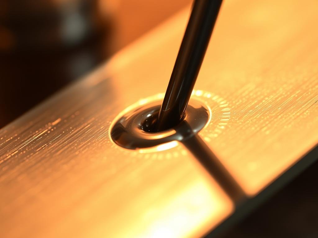
CNC‑machined enclosures, heat sinks, and fixtures for stable soldering
Custom machined heat sinks and fixtures improve thermal uniformity during reflow and hand work.
Even heat spreaders reduce tombstoning, skew, and variable wetting across boards.
Material pairing and tolerance control to mitigate thermal stress
Matching CTE values between metals and plastics limits thermal expansion mismatch and protects joints.
Tight tolerance carriers keep planarity and alignment, lowering stress concentrations during heating and cooling.
From prototype to mass production: Rapidaccu’s 15+ years of precision
Rapidaccu iterates prototype fixtures quickly, validating thermal performance before scale‑up.
Clients gain consistent surface finish, accurate parts, and integrated locating pins or embedded heat spreaders for repeatable runs.
- Titanium liners or impellers help lead‑free wave runs reduce pot maintenance from high‑tin scavenging.
- Nickel additions stabilize copper‑tin intermetallics and improve appearance after solidification.
- Design, process, and machining collaboration optimizes profiles, alloy behavior, and throughput.
| Feature | Benefit | Manufacturing impact |
|---|---|---|
| CNC heat spreader | Even temperature across board | Fewer defects; higher yield |
| Tight tolerance carrier | Maintains planarity | Less warpage and pad stress |
| Material pairing (metal/plastic) | Matched thermal expansion | Longer joint life; fewer cracks |
| Prototype iteration | Validated thermal behavior | Smoother scale to mass production |
Conclusion
Document alloys, flux choices, and profile targets so teams repeat quality from prototype to volume. Key data—Sn63/Pb37 at 183°C, SAC305 near 221°C solidus, Sn99.3/Cu0.7 at 227°C—guide setpoints and safe handling for FR-4 that softens near 130–140°C.
Use reflow peaks around 220–249°C for lead-free solder and wave pots near 240–260°C. Allow thermal headroom to ensure full wetting while protecting board and components.
Maintain cleanliness, match flux chemistry to alloy, and verify surface finish after cooling. Inspect fillets and train operators on wire technique for consistent hand work.
Rapidaccu stands ready to support programs with precision CNC fixtures, heatsinks, and parts that stabilize temperature control and improve consistency across electronics runs.