
Precision CNC Machined Motor Housings
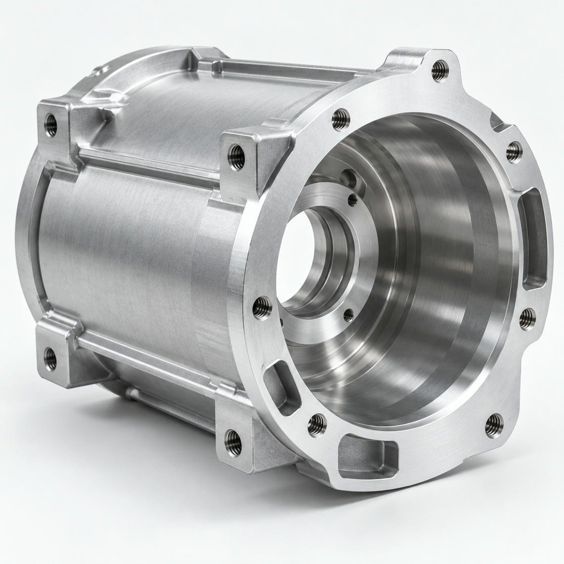
Custom motor casings, end caps and flanged housings with controlled bearing bores, mounting interfaces and concentric features, from prototype to production orders.
Bearing Bores
Controlled fits
Concentricity
Datum-based
Inspection
Drawing-driven
Why Precision Matters
When Motor Housing Accuracy Matters
A motor housing is a structural component of the drive system. Its geometry influences bearing alignment, motor assembly, shaft positioning, and the relationship between stationary and rotating components.
Poorly controlled bearing seats or mounting interfaces can contribute to vibration, assembly difficulties, and premature mechanical wear.
Rapidaccu supports custom motor housing manufacturing with CNC turning, precision milling, multi-axis machining, and drawing-based inspection planning. We manufacture customer-designed metal motor housings for prototypes, development programs, and production orders.
Product Scope
Motor Housing Components We Manufacture
Cylindrical Motor Casings
Machined shells with controlled inner diameters, wall thicknesses, mounting details, and external interfaces.
Motor End Caps
Front and rear covers featuring bearing pockets, locating diameters, fastening holes, and mating surfaces.
Flanged Motor Housings
Integrated cylindrical bodies and mounting flanges designed for secure installation.
Servo and BLDC Motor Housings
Custom housings for servo and brushless DC motor assemblies, manufactured according to supplied mechanical drawings.
Motor Mounting Structures
Precision interfaces connecting motor housings to robotic joints, gear reducers, or industrial equipment.
Geometric Control
Three Critical Relationships in Motor Housing Machining
Bearing Bore to Housing Axis
The bearing seat must maintain the required positional relationship to the designated housing datum axis.
Rapidaccu evaluates turning and boring sequences to reduce unnecessary re-clamping of critical cylindrical features.
Front Mounting Face to Bearing Axis
The mounting face influences how the motor aligns with the connected equipment.
Face runout, perpendicularity, and flatness requirements should be defined according to actual assembly needs.
Front and Rear Bearing Seat Alignment
Where a housing contains multiple bearing locations, coaxial alignment becomes especially important.
The inspection method should be selected based on the drawing’s datum system and geometrical tolerances.
Process Planning
Typical Machining Strategy
Establish Functional Datums
Identify bearing seat axes, mounting faces, and primary locating surfaces before developing the machining sequence.
Machine the Housing Body
Use CNC turning, milling, or a suitable combination to produce the main external and internal geometry.
Finish Critical Features
Machine bearing bores, locating shoulders, mounting interfaces, and threaded features according to specified tolerances.
Inspect Assembly-Critical Dimensions
Apply appropriate bore measurements, CMM inspection, or runout measurement to verify the specified characteristics.
Materials
Material Selection for Motor Housings
| Material | Engineering Consideration |
|---|---|
| Aluminum 6061-T6 | Low weight, good machinability, useful thermal conductivity |
| Aluminum 7075-T6 | Higher structural strength for selected lightweight designs |
| Stainless Steel | Corrosion resistance and strength, with increased weight |
| Carbon Steel | Structural rigidity and mechanical strength |
| Cast Iron | Useful damping characteristics for selected machinery applications |
Material selection should account for bearing retention, operating temperature, vibration, environment, and production cost.
RFQ Preparation
Engineering Checklist Before Requesting a Quote
Provide the following information whenever possible:
- Bearing bore diameter and specified fit
- Primary datum axis and mounting reference surface
- Concentricity, position, and runout requirements
- Surface roughness of functional bearing seats
- Heat treatment or coating specifications
- Planned assembly method and operating conditions
- Expected prototype and production quantities
Important
Very tight tolerances should be assigned only where they affect function.
Excessive tolerancing across noncritical surfaces can increase machining and inspection cost without improving motor performance.
Get a Tolerance Review
Production Workflow
From Motor Prototype to Repeat Production
Rapidaccu’s manufacturing workflow combines engineering review, machining process planning, dimensional inspection, and material documentation as required.
For repeat orders, critical dimensions and inspection requirements can be defined at the quotation stage to support consistent production.
Discuss Your Motor Housing Requirements
Whether you need a cylindrical motor shell, precision end cover, or complex flanged housing, our team can review your drawing for machining feasibility.
Send Your Motor Housing CAD FilesContact Us
Request a Motor Housing Quote
Share your CAD model, 2D drawing with GD&T, material, finish, and quantities. Our engineers will review machining feasibility and critical features.
Send Your Requirements
Fill in the form and attach your files.