
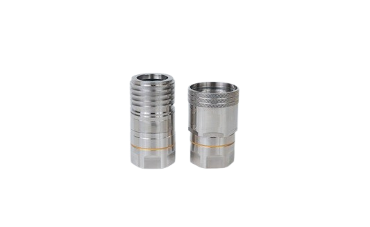
OCP LQC Large-Flow Quick Couplings: 20 mm Flow Path, Screw-to-Connect Lock, Vibration-Resistant Reliability
Rapid-connect and serviceable fluid coupling solution for large cold-plate systems and high-flow thermal management loops—engineered for maximum flow with minimum pressure drop.
OCP LQC Engineered
20 mm Flow Path
Screw-to-Connect
Tactile Confirmation
Vibration Resistant
What Is LQC & Where Large-Flow Matters
LQC Defined
LQC (Large Quick Coupling) is a large-bore, high-flow-capacity quick-connect coupling designed for thermal management systems where standard coupling diameters create unacceptable pressure drop. With a 20 mm nominal flow path, LQC delivers the volume flow rate that high-heat-load cold plates and main cooling loops demand.
Large Cold-Plate Systems
Single-plate high-heat-load applications with multi-channel parallel flow requiring maximum coolant throughput at minimal restriction.
High-Flow Trunk Lines
Main supply/return distribution loops where pressure drop at the coupling directly impacts total system pumping cost and thermal performance.
Vibration-Prone Environments
Equipment with mechanical vibration where push-to-connect couplings risk loosening. Screw-to-connect provides positive mechanical lock retention.
Key Benefits
Lower system ΔP, higher thermal capacity headroom, stronger connection integrity, faster maintenance with tool-free hand-tightening.
System Integration Scope
Interface Dimensions
Port sizing, face geometry, and bolt patterns aligned with OCP LQC interface framework
Component Compatibility
Designed to interface with cold plates, manifolds, flexible/rigid tubing per OCP ecosystem conventions
Documentation Support
Specifications, inspection reports, traceability records, and compliance documentation available
Designed to OCP LQC Standards
Our LQC coupling series is engineered per OCP LQC specifications for large-bore liquid cooling quick-connect interfaces. The design addresses dimensional, performance, and reliability criteria defined for high-flow-rate coupling systems within the OCP thermal management ecosystem.
20 mm Nominal Flow Path: The Low-ΔP Advantage
A 20 mm internal bore provides dramatically higher flow capacity and lower pressure drop compared to smaller couplings. For large cold-plate systems and high-flow trunk lines, this translates directly into better thermal performance, lower pumping energy, and more headroom for system expansion.
Higher Volume Flow Rate
Larger bore cross-section handles significantly more coolant volume per unit time at any given velocity.
Lower Pressure Drop at Same Flow
ΔP scales inversely with bore diameter—a 20 mm path delivers substantially lower restriction than 12 mm or 8 mm couplings.
Large Cold-Plate Friendly
Feeds high-surface-area cold plates and multi-channel parallel flow architectures without starving downstream circuits.
Pressure Drop Factors
System ΔP is influenced by multiple factors beyond the coupling alone. To provide an accurate pressure-drop assessment for your application, we need:
Screw-to-Connect & Tactile Confirmation
Engagement Sequence
Align & Insert
Position the coupling halves coaxially and push plug into receptacle until guide features engage.
Screw to Lock
Rotate the locking collar by hand. Thread engagement progressively draws the halves together and compresses the seal.
Tactile Stop
A definite tactile stop confirms full engagement. The connection is locked, sealed, and ready for pressurization.
Why Screw-to-Connect?
Superior Pull-Out Resistance
Thread engagement provides mechanical interlock far stronger than spring-latch push-to-connect designs.
Vibration-Proof Retention
Threaded lock cannot disengage under vibration—critical for equipment with rotating machinery or transport exposure.
Unambiguous Assembly State
Tactile hard-stop eliminates “partial insertion” risk. Operators know with certainty when the connection is complete.
Foolproof Design
Anti-cross-thread features and keying prevent incorrect assembly. Visual lock-state indicator available.
Superior Sealing Under Pressure & Vibration
Seal Architecture
Precision-engineered face-seal and O-ring interfaces with controlled compression ratios. Seal groove geometry is optimized for the LQC’s 20 mm bore to maintain consistent contact stress under full system pressure.
Pressurized Seal Performance
The screw-to-connect mechanism provides controlled, repeatable seal compression with every connection cycle. Thread engagement force is independent of operator hand strength, ensuring consistent sealing at rated pressure across all installations.
Pressure-assisted sealing: higher system pressure increases seal contact force.
Vibration Resistance
The threaded locking collar provides inherent anti-vibration retention without additional locking hardware. Anti-loosening design elements may include:
Mounting, Termination & Layout
Mounting Forms
Termination Options
Layout Direction
All configurations available with screw-to-connect locking mechanism.
Engineered for Large Cold-Plate System Integration
Engineering-configurable platform. Every parameter below is open for customization to match your system requirements.
| Dimension | Default Direction | Customizable Scope | Customer Provides | Rapidaccu Delivers |
|---|---|---|---|---|
| Interface & Mounting | Cold-plate / manifold mating | Mounting face, hole pattern, seal geometry | Cold-plate interface drawing, datum | Interface design + DFM review |
| Flow / ΔP Target | 20 mm large-bore, low ΔP | Flow-path optimization, transitions | Target flow, ΔP budget, loop diagram | ΔP assessment + optimization |
| Locking & Tactile | Screw-to-connect | Lock stroke, stop design, torque window | Assembly method, workstation capability | Lock design + validation criteria |
| Material & Surface | Corrosion-resistant, high-strength | SS / AL / brass, plating / passivation | Media, environment grade | Material + surface recommendation |
| Seal Material | Reliable elastomer sealing | EPDM / FKM, hardness, cross-section | Temperature, media, life target | Compatibility advisory + test plan |
| Reliability Targets | Vibration & pressure rated | Vibration class, cycle life, leak target | Acceptance standards | Test plan + acceptance report |
| Cleaning & Packaging | Large-bore cleaning | Cleanliness level, plugs, labeling | Cleanliness requirements | Cleaning + packaging spec |
| Documentation | Engineering project delivery | FAI, inspection reports, traceability | Document checklist | Project documentation package |
Pressure Drop, Burst, Vibration & Cycle Life Evidence
Verification Capabilities
Leak Detection
Pneumatic and hydrostatic leak testing with quantified leak-rate reporting at rated and proof pressure.
Pressure Hold & Burst
Proof at 2× rated, optional burst at 4×. Sustained pressure-hold verification with zero-deformation criteria.
Vibration Seal Retention
Seal integrity verification under defined vibration profiles—confirming screw-lock prevents loosening and seal degradation.
Connect/Disconnect Cycle Life
Repeated screw-connect/disconnect cycles with leak-rate measurement to validate long-term seal and thread performance.
Inspection & Output
Deliverables
Inspection Reports
Batch Traceability
Material Certificates
Test Certificates
Large-Bore Seal-Face Consistency at Scale
CNC Critical-Surface Machining
Multi-axis CNC milling and turning produce the large-diameter seal faces, bore transitions, and thread profiles that LQC demands. Key machining controls:
Post-Machining & Volume Consistency
Surface treatment, cleaning, assembly, functional test, and packaging—all controlled for large-bore coupling quality:
15 Years of Precision Manufacturing. Rapidaccu delivers large-bore coupling components with the surface quality, thread precision, and seal-face consistency that high-flow liquid cooling systems demand.
For Cold-Plate System Engineers
Align & Insert
Position coupling halves coaxially. Push plug into receptacle until guide features engage and coupling is seated.
Screw to Lock Position
Hand-tighten the locking collar. Rotate until the tactile hard-stop is felt—no tools required under normal conditions.
Confirm & Pressurize
Verify tactile confirmation and visual lock indicator (if equipped). The system is ready for pressurization.
Maintenance Disconnect
Depressurize system. Unscrew locking collar and withdraw plug. Dry-break valves contain residual fluid on both halves.
Torque & Handling
Recommended tightening approach and torque range are provided in the product specification document. Under standard conditions, hand-tightening to the tactile stop is sufficient. For applications with specific torque requirements, contact our engineering team for the validated torque specification for your configuration.
Anti-Vibration Guidance
LQC in Large Cold-Plate & High-Flow Systems
Large Cold-Plate Systems
High-surface-area cold plates with multi-channel parallel flow. LQC’s 20 mm bore delivers the volume flow rate these plates demand without creating a bottleneck at the coupling connection.
High-Flow Trunk Connections
Main supply and return lines in rack-level or facility-level cooling distribution. Every mbar of coupling ΔP saved translates directly into reduced pumping energy across the fleet.
Vibration-Exposed Equipment
Industrial cooling systems with compressors, fans, or rotating machinery. Screw-to-connect locking provides mechanical security that push-connect designs cannot match under sustained vibration.
Cabinet-Level Primary Connections
Main liquid cooling connections at the cabinet or rack boundary. LQC provides the high-flow, high-reliability serviceable connection point for primary cooling loop management.
Project-Level Quality Assurance
Incoming Material
Certs, hardness, stock dimensions
In-Process SPC
CTQ dimensions at critical operations
Final Inspection
100% critical dims, leak, visual, pack
Batch/serial number coding
Material-to-part linkage
Process parameter records
Test result archive
Document change control
FAI / first-article packages
Material certificates (MTR)
RoHS/REACH support
Customer-format reports
Source inspection welcome
OCP LQC Large-Flow Coupling FAQ
How much can the 20 mm flow path improve system pressure drop?
Does screw-to-connect require tools? How do I confirm full engagement?
How is vibration resistance verified? What test reports are available?
How do I select the right seal material for my coolant?
Can you customize the LQC to mate with my cold plate or manifold interface?
What are lead times, MOQ, and documentation deliverables?
Start Your LQC Large-Flow Project
Share your cold-plate interface drawings, flow requirements, and system parameters. Our engineering team responds within 24 hours with a feasibility assessment and tailored proposal.
Address
Rongli Industrial Park, Dalang, Longhua District, Shenzhen, China
Experience
15 Years of Precision Manufacturing
Response
Engineering review within 24 hours
Request a Quote
Upload your cold-plate/manifold interface drawings or describe your large-flow coupling requirements.