
MQD Multi Quick Disconnect: Built for Compute Tray Tight Spaces—Ultra-Small, High Flow, Low Pressure Drop
Straight and right-angle multi-circuit couplings engineered for high heat-flux density and demanding thermal environments, enabling rapid assembly and field serviceability.
What Is MQD & Why It Fits Compute Trays
MQD Defined
Multi Quick Disconnect (MQD)—a multi-circuit, multi-channel rapid disconnect coupling engineered to connect and disconnect multiple fluid paths simultaneously in a single compact interface, purpose-built for compute tray and high-density cooling applications.
Extreme Space Constraints
Compute trays and drawers leave millimeters—not centimeters—for fluid connections. Dense tubing runs compete with power, signal, and airflow paths.
Rapid Plug-Pull Maintenance
Every second of downtime costs revenue. Trays must be swapped, serviced, and returned to operation in minutes, not hours.
High Thermal Load Stability
Sustained high heat flux demands stable flow rates and leak-proof sealing through thermal cycling, vibration, and repeated maintenance events.
Typical Integration Points
Tray ↔ Manifold
Multi-channel tray-to-manifold quick disconnect interface
Tray ↔ CDU Branch
Direct tray connection to CDU supply/return lines
Slide-In Module
Rail-mounted module auto-connect on insertion
Multi-Path Hub
Centralized multi-loop distribution point within trays
Small Body. High Flow. Low ΔP. The Engineering Logic.
Ultra-Small Profile
Every millimeter matters inside a compute tray. MQD’s minimized envelope delivers:
High Flow, Low ΔP
Maximizing flow while minimizing pressure drop through:
Reliable Sealing
Sustained sealing performance under demanding conditions:
Multi-Channel Connect, Seal & Disconnect
Connection Sequence
Alignment & Guide
Guide features on the multi-port interface capture and steer all channels toward their corresponding ports simultaneously.
Insertion & Seal Engagement
All channels engage their respective sealing surfaces with controlled compression. Valves begin opening across all circuits.
Lock & Full Flow
Positive latch engages with tactile confirmation. All flow paths are fully open and leak-tight at system pressure.
Disconnect & Multi-Channel Consistency
Controlled Disconnect
Upon release, all channel valves close simultaneously. Residual fluid is controlled to minimal trace volumes on each port. Dual-poppet dry-break architecture prevents air ingress into the active cooling loop.
Multi-Channel Alignment Criticality
Simultaneous multi-port docking demands tight parallelism and position tolerance between channels. The MQD interface is designed to:
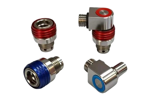
Straight / Right-Angle & Multi-Channel Arrangements
Straight (Inline)
Axial flow path with minimal internal redirection. Optimal for straight-through tubing runs where height clearance is available. Lowest possible pressure drop per channel.
Best for: Linear routing with axial clearance
Right-Angle (90°)
90° flow redirection within the coupling body. Designed for height-restricted zones where tubing must exit perpendicular to the connection axis. Internal radius optimized for ΔP control.
Best for: Low-profile trays and vertical-space-limited areas
Multi-Channel Combinations
2-channel, 4-channel, or more—configured per your tray’s cooling circuit count. Available as monolithic multi-port bodies or modular assemblies, depending on project requirements.
Customizable channel count, pitch, and port arrangement
Selection Tip: Use right-angle configurations where tray height is constrained and tubing must exit laterally. Use straight configurations for direct-line connections with the lowest pressure penalty. Our engineering team can recommend the optimal layout for your specific tray geometry and ΔP budget.
Engineered Around Your Compute Tray Integration
Not a catalog product—an engineering-configurable platform. Tell us your constraints, we deliver the solution.
| Dimension | Default Direction | Customizable Scope | Customer Provides | Rapidaccu Delivers |
|---|---|---|---|---|
| Channel Count & Layout | Multi-circuit parallel docking | Channel count, pitch, layout, isolation | Circuit count, tray interface drawing | Layout design + tolerance chain |
| Envelope Height | Ultra-small profile | Height, latch position, clearance optimization | Space envelope, interference zones | Structure optimization + DFM |
| Straight / Right-Angle | Straight & Right-angle | Angle, turn radius, exit direction | Routing direction, assembly sequence | Routing & assembly advisory |
| Flow / ΔP Target | High flow, low pressure drop | Flow-path size, valve parameters | Target flow rate, ΔP budget | ΔP assessment + optimization proposal |
| Interface Termination | Barb / Threaded / Manifold face | Custom barbs, threads, adapters, face seal | Tube ID / thread / mounting face | Interface DFM + seal advisory |
| Seal System | Reliable multi-channel sealing | Seal material, structure, temp/chemical rating | Coolant formula, temperature range | Compatibility advisory + validation |
| Material & Surface | Corrosion-resistant / Lightweight | AL / SS / Brass / Engineering plastic | Environment class, corrosion risk | Material + surface recommendation |
| Assembly & Positioning | Tray blind / quick-mount | Guides, keying, locating pins | Assembly method, datum reference | Guide / positioning design |
| Testing & Documentation | Project delivery package | Leak / pressure / cycle tests, FAI | Acceptance criteria, doc format | Test plan + report package |
Evidence Chain for Pressure Drop, Flow & Thermal Endurance
Key Performance Parameters
Verification Capabilities
Leak Test
Air / He detection
Pressure Hold
Proof & burst capable
CMM Dimensional
GD&T verification
Surface Inspection
Ra & finish quality
Deliverable Documentation
Space, Tolerance & Assembly Sequence for Multi-Channel Docking
Tolerance Chain for Multi-Port Docking
Multi-channel simultaneous engagement amplifies sensitivity to port-to-port parallelism and position accuracy. Design the mating interface with the full tolerance chain in mind: tray mounting datum → manifold face → connector locating features → individual port axes. Our engineering team provides stack-up analysis to ensure reliable multi-channel docking within your system tolerances.
Recommended Positioning Strategy
Use locating pins or guide tapers on the multi-port body to register the coupling to the manifold before individual channels engage seals. Consider floating-mount options to absorb positional deviation between the tray and the manifold mounting surface.
Assembly Sequence
Position first, lock second. Ensure guide features are fully engaged before applying insertion force to the sealing zone. Route harnesses and tubing bundles clear of the coupling engagement path. Confirm all channels are seated via tactile/audible lock feedback.
Maintenance & Tray Swap
Single-action release disconnects all channels simultaneously. Dry-break valves contain fluid on both halves, minimizing drip and air ingress. Designed for sub-minute tray removal and replacement without draining the cooling loop or handling individual connections.
Caution Notes
Miniature-Part Consistency & Yield Control
CNC Precision Advantage
Multi-axis CNC milling and mill-turn machines micro-scale flow channels, seal grooves, and mating surfaces in the compact MQD envelope with sub-micron repeatability. 5-axis capability enables complex internal flow paths that minimize ΔP.
Critical Quality Controls
Post-Machining & Delivery
Surface treatment, ultrasonic cleaning, seal-kit assembly, functional leak test, dust-cap protection, and cleanroom-grade packaging—all executed within our controlled production flow before shipment.
15 Years of Precision Manufacturing. Rapidaccu delivers miniature fluid coupling components with the dimensional consistency and surface quality required for high-density compute tray cooling—from prototype through volume production.
MQD in High-Density Thermal Management Systems
Compute Tray Quick-Service Interface
Slide-in and drawer-style compute trays with multi-channel MQD connections for instant fluid loop engagement on insertion and zero-tool disconnection for hot-swap maintenance.
GPU / AI Server Tray Cooling
High thermal density GPU and AI accelerator trays requiring maximum flow per available space. MQD’s ultra-small profile and low ΔP enable effective cooling without compromising tray layout density.
Manifold-to-Module Multi-Path
Centralized manifold distribution to multiple cooling zones within a single module or chassis, using MQD as the single-point multi-channel disconnect for each module boundary.
Space-Constrained Industrial Thermal
Beyond data centers—any industrial thermal management module where space is at a premium and multi-circuit quick-disconnect is required: power electronics, medical devices, laser systems, and more.
From Concept to Volume: Our Collaboration Model
Engineering Services
DFM & Tolerance Chain Analysis
Multi-port parallelism, seal-groove manufacturability, and assembly-stack review
Flow & ΔP Target Decomposition
Structural optimization recommendations backed by simulation or empirical data
Cost Optimization
Material, machining-strategy, and design-for-cost suggestions without compromising function
Material & Surface Advisory
Coolant compatibility, corrosion strategy, and surface-finish selection guidance
Project Timeline
Requirements Review
Week 1System constraints, tray geometry, flow/ΔP targets, interface definition
Concept & DFM
Week 2–3Layout, structure, tolerance chain, machining feasibility, cost estimate
Prototype & Validation
Week 3–6Functional samples, ΔP measurement, leak test, assembly verification
Volume Ramp-Up
Week 6+Production tooling, SPC, pilot batch, volume manufacturing with full QC
Delivery Confidence for Global Customers
Inspection Framework
Three-stage quality gate: incoming material verification, in-process SPC at critical operations, and comprehensive final inspection including dimensional, leak, and visual checks.
Batch Traceability
Every MQD unit is linked to its material lot, machining batch, test results, and inspection records via unique batch/serial coding. Full audit trail from raw stock through shipment.
Deliverable Documentation
FAI / first-article packages, material certificates, dimensional and leak-test reports, compliance documentation (RoHS/REACH)—formatted to your QA system requirements.
MQD Multi Quick Disconnect FAQ
Does multi-channel docking require very tight installation tolerances?
How do I choose between straight and right-angle to minimize pressure drop?
Can you assess system pressure drop? Do you offer simulation or test support?
Will parallel multi-channel layouts cause thermal or structural interference?
Can you customize channel count, pitch, and mounting face interface?
What are prototype and production lead times? Is there a minimum order?
Start Your MQD Compute Tray Project
Share your tray geometry, circuit requirements, and ΔP targets. Our engineering team will respond with a feasibility assessment and custom MQD proposal within 24 hours.
Address
Rongli Industrial Park, Dalang, Longhua District, Shenzhen, China
Experience
15 Years of Precision Manufacturing
Response
Engineering review within 24 hours
Request a Quote
Upload your tray interface drawings, space envelope, or describe your multi-circuit cooling requirements.