
OCP Standard UQD Quick Disconnect Couplings: Aerospace-Grade Sealing, Bidirectional Dry-Break, Plug-and-Play
Covering sizes 02–08, available in Inline (straight-through) and Right-angle configurations, with multiple Barb and Threaded termination options for maximum system flexibility.
What Is a UQD & What Problems Does It Solve?
Rapid Fluid Connection
UQD (Universal Quick Disconnect) couplings provide tool-free, instant connections within liquid-cooling and fluid loops, drastically reducing downtime for maintenance and component swaps.
Standardized & Scalable
Engineered per OCP specifications, UQD couplings ensure cross-vendor interoperability, simplified inventory management, and seamless system expansion without redesign.
Minimized Leak Risk
The bidirectional dry-break valve mechanism self-seals both halves upon disconnection, virtually eliminating fluid spillage, air ingress, and contamination risks in your loop.
Typical Systems & Integration Points
Cold Plates
Direct-to-chip cooling modules
Manifolds
Distribution and collection headers
CDU Systems
Coolant Distribution Units
Rack/Chassis Loops
Cabinet internal circulation
OCP Compliant
Engineered per Open Compute standards
Engineered per OCP Standards
Our UQD couplings are designed and manufactured with reference to relevant OCP (Open Compute Project) specifications for liquid cooling quick-disconnect interfaces. We provide detailed compliance scope documentation upon request to ensure transparent alignment with your system requirements.
Coolant Compatibility
Verified for common liquid-cooling media including water-glycol mixtures, with adaptation strategies for proprietary formulations.
System Pressure & Temperature
Designed for typical data-center liquid-cooling pressure and temperature operating envelopes with safety margins.
Interface Standardization
Port dimensions, thread forms, and sealing profiles follow industry-common conventions ensuring broad interchangeability.
OCP Quick Glossary
OCP = Open Compute Project, an industry consortium defining open-source hardware standards for data centers. UQD = Universal Quick Disconnect, the standardized coupling interface for modular liquid-cooling systems.
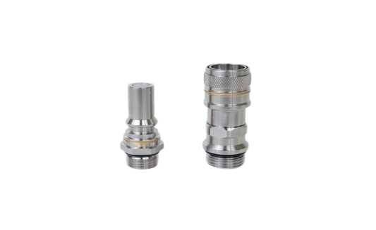
Sealing + Dry-Break Valve + Bidirectional Design
Bidirectional Dry-Break Valve
The core of every UQD coupling features a precision-engineered bidirectional dry-break valve mechanism. When disconnected, both the male and female halves automatically seal via spring-loaded poppet valves, preventing fluid leakage and air ingress.
Connected State: Both poppets open simultaneously, creating an unobstructed flow path with minimal restriction.
Disconnected State: Springs return both poppets to the closed position, forming a tight seal on each half independently.
Aerospace-Grade Sealing
Multiple sealing barriers—including precision O-rings and face seals—are engineered into critical interfaces. Seal groove geometry, surface finish, and compression ratios are controlled to aerospace-class tolerances for repeatable, reliable performance.
O-Ring Seals: Radial and axial sealing at connection interfaces with controlled squeeze ratios.
Face Seals: Flat-face sealing surfaces lapped to stringent flatness specs for zero-leak performance.
Plug-and-Play Experience
Intuitive connection by design. Alignment guides ensure correct orientation on approach. The coupling engages with a positive tactile click confirming secure lock. No tools, no torque wrenches, no training required.
Single-Handed Operation: Push to connect, press release to disconnect.
Audible Confirmation: Tactile and audible feedback confirms full engagement.
Foolproof & Anti-Misconnect
Keying and polarization features prevent incorrect mating between different size or circuit couplings. Guide rails ensure axial alignment before the valve mechanism engages, protecting internal seals from damage during insertion.
Keyed Configurations: Available keying options prevent cross-connection between circuits.
Guided Entry: Chamfered and piloted interfaces ensure smooth, damage-free engagement.
Size Selection Matrix: Sizes 02–08
Choose the right UQD coupling for your application using the matrix below. All sizes are available in Inline and Right-angle configurations with Barb or Threaded terminations.
| Size | Configuration | Termination | Seal Type | Valve Type | Suggested Flow Range |
|---|---|---|---|---|---|
| UQD-02 | Inline / Right-angle | Barb / Threaded | O-ring | Dry-break | 0.5–1.5 LPM |
| UQD-03 | Inline / Right-angle | Barb / Threaded | O-ring | Dry-break | 1.0–3.0 LPM |
| UQD-04 | Inline / Right-angle | Barb / Threaded | O-ring / Face | Dry-break | 2.0–5.0 LPM |
| UQD-05 | Inline / Right-angle | Barb / Threaded | O-ring / Face | Dry-break | 3.0–8.0 LPM |
| UQD-06 | Inline / Right-angle | Barb / Threaded | O-ring / Face | Dry-break | 5.0–12.0 LPM |
| UQD-07 | Inline / Right-angle | Barb / Threaded | Face seal | Dry-break | 8.0–18.0 LPM |
| UQD-08 | Inline / Right-angle | Barb / Threaded | Face seal | Dry-break | 12.0–25.0 LPM |
Select by Flow & Pressure Drop
Match the coupling size to your system’s required flow rate and allowable pressure drop. Larger sizes provide lower restriction at higher flow rates.
Select by Routing Space
Choose Right-angle for tight-bend routing or restricted vertical clearance. Choose Inline for straight-through routing with ample axial space.
Select by Assembly Method
Barb terminations for flexible tubing with clamp retention. Threaded terminations for rigid connections, manifolds, or hard-line assemblies.
Barb & Threaded Terminations
Barb (Hose Barb) Termination
Hose Compatibility
Designed for flexible tubing—silicone, EPDM, PVC, and reinforced rubber hoses. Barb profiles optimized for different durometer ratings (50A–80A Shore hardness).
Clamp Recommendations
Worm-drive clamps for general use; spring clamps for constant-tension applications; crimp rings for production-volume, tamper-resistant assemblies.
Assembly Notes
Lubricate barb with compatible fluid before insertion. Push hose fully past all barb ridges. Position clamp behind the last barb for maximum retention. Verify pull-off resistance per your specification.
Available barb sizes are matched to standard tubing IDs across the 02–08 size range.
Threaded Termination
Thread Standards
Available in NPT, G (BSPP), M (Metric) thread forms. Custom thread specifications can be accommodated for special manifold or panel-mount applications.
Sealing Methods
PTFE tape for NPT tapered threads; bonded washers or face-seal O-rings for parallel threads (G/M); anaerobic thread sealant for permanent installations.
Torque & Installation
Torque specifications provided per thread size and material combination. Anti-galling coatings available for stainless-steel-to-stainless-steel joints.
Threaded terminations suit rigid plumbing, manifold blocks, and panel-mount pass-through configurations.
Custom & Special Terminations
Engineered for Your Media, Environment & Lifecycle
Body Materials
Stainless Steel (303/304/316L)
Maximum corrosion resistance, ideal for aggressive coolants and high-purity loops.
Aluminum Alloy (6061-T6 / 7075)
Lightweight, excellent thermal conductivity, anodizable for enhanced surface protection.
Brass / Copper Alloy
Good machinability and antimicrobial properties, suited for water-based coolant systems.
High-Performance Engineering Plastics
PEEK, PPS, or POM for weight-critical or electrically-insulating applications.
Seal Materials
EPDM
Excellent resistance to water-glycol mixtures, broad temperature range (-40°C to +150°C).
FKM (Viton®)
Superior chemical resistance for aggressive or fluorinated coolants and elevated temperatures.
NBR (Nitrile)
Cost-effective general-purpose seal material with good abrasion resistance.
Surface Treatments
Coolant Compatibility Advisory: We recommend chemical compatibility validation between your specific coolant formulation and the selected body/seal materials. Rapidaccu can support immersion testing upon request.
Tested for Sealing, Pressure, Life & Cycle Endurance
Leak Rate
<0.1 cc/min
Typical at rated pressure, verified by helium or air-under-water testing
Proof Pressure
2× Rated
Proof-tested at 2× working pressure with zero deformation or leakage
Connect Cycles
10,000+
Validated connect/disconnect cycles maintaining seal integrity
Key Performance Parameters
Testing Capabilities
Pneumatic & Hydrostatic Leak Test
Air-under-water and pressurized-hold leak detection with quantified leak-rate reporting.
Pressure Hold & Burst Test
Sustained pressure testing and destructive burst verification per applicable standards.
Dimensional & Visual Inspection
CMM measurement, optical comparator, surface roughness profiling, and visual inspection under magnification.
Material & Hardness Verification
Material certs (MTR), hardness testing, and chemical composition analysis available on request.
Full batch traceability and inspection records provided with every shipment. Lot-coded for your incoming quality assurance.
How Rapidaccu Manufactures Your UQD Couplings
Combining engineering-driven precision machining with multi-process capabilities, we deliver UQD components from prototype to volume production with full quality traceability.
CNC Precision Machining
3-axis, 4-axis, and 5-axis CNC milling plus multi-axis CNC turning and mill-turn centers for complex internal geometries, valve seats, and seal grooves in a single setup.
Critical Control Points
- Seal face roughness ≤ Ra 0.4 μm
- Concentricity / TIR ≤ 0.01 mm
- Valve seat & groove consistency
- Bore finish & dimensional tolerance
EDM & Wire EDM
Sinker and wire EDM for intricate internal features, sharp internal corners, and thin-wall geometries that conventional machining cannot achieve with required precision.
Prototype to Production
Rapid prototyping in 5–7 business days. Pilot batch validation. Scalable ramp-up to volume production with consistent process controls and SPC monitoring.
Surface Treatment
In-house and certified partner surface finishing—anodizing, nickel plating, passivation, electropolish—integrated seamlessly into the manufacturing flow.
Clean, Pack & Assemble
Ultrasonic cleaning, lint-free drying, dust-cap protection, and optional sub-assembly or complete coupling assembly with tested seal kits before shipment.
15 Years of Precision Manufacturing Experience. Rapidaccu combines deep engineering expertise with advanced multi-axis machining, delivering quality UQD components that meet the tightest specifications, on schedule.
Custom Development: From Requirements to Manufacturable Design
Input Information Checklist
Providing these details upfront accelerates our engineering response and ensures an accurate, optimized proposal:
Flow & Pressure
Target flow rate, allowable pressure drop, system operating pressure
Temperature & Media
Operating temperature range, coolant type/formulation, chemical additives
Space & Interface
Installation envelope, mating interface form, panel-mount requirements
Lifecycle & Usage
Target service life, connect/disconnect frequency, maintenance interval
Standards & Documentation
RoHS/REACH compliance, material certificates, specific test requirements
DFM & Design Optimization
Tolerance Advisory
Recommend functional tolerances that balance performance with manufacturability
Seal Architecture Review
Seal groove geometry, compression ratio, and backup ring recommendations
Material & Finish Selection
Optimal material/surface treatment pairing for your application and cost target
Cost Optimization
Design-for-cost suggestions without compromising functional requirements
Prototype Iteration Process
Round 1: Concept Prototype
Validate form, fit, and basic function. 5–7 business days.
Round 2: Functional Validation
Pressure, leak, and cycle testing. Refinements based on test data.
Round 3: Pre-Production Pilot
Production-intent tooling and process. Final sign-off before volume ramp.
Your Evidence for Confident Volume Production
Inspection Flow
Incoming Material Verification
Raw material certs, hardness checks, dimensional verification of stock
In-Process Inspection
SPC monitoring, first-piece verification, critical dimension checks at key operations
Final Inspection & Test
100% dimensional check on critical features, leak test, visual inspection, packaging audit
Documentation Package
Inspection Reports
Dimensional, leak-test, and pressure-hold results
Material Certificates
Mill test reports, chemical composition, heat-treat records
Batch Traceability
Unique lot codes linking each part to raw material, process, and test data
Test Certificates
Leak-rate data, pressure-hold confirmation, cycle-test summaries
Customer Acceptance Support
First Article Inspection (FAI)
Comprehensive first-article packages with ballooned drawings, measured values, and pass/fail disposition per AS9102 or customer-specified formats.
PPAP Support
Production Part Approval Process documentation available for automotive-style qualification requirements.
Source Inspection Welcome
On-site source inspection and audit visits accommodated at our Shenzhen facility.
UQD Couplings in Real-World Systems
See how our OCP-standard UQD couplings integrate into critical fluid systems across industries.
Rack-Level Liquid Cooling Maintenance
Hot-swap server trays or cooling modules without draining the entire rack loop. UQD dry-break valves eliminate spillage in live data center environments, reducing maintenance time from hours to minutes.
CDU & Manifold Modular Connection
Standardized UQD interfaces at CDU outlets and manifold inlets enable modular system architectures. Add capacity, reconfigure distribution, or replace units without custom plumbing—just connect and go.
Equipment Internal Circulation Loop
Serviceable connection points within enclosed equipment allow individual cooling modules—cold plates, heat exchangers—to be replaced independently during field maintenance without specialized tooling.
High-Density Routing (Right-Angle Advantage)
In space-constrained chassis and blade servers, right-angle UQD couplings minimize bend radius and vertical clearance requirements, enabling denser packaging without compromising serviceability or flow performance.
From Inquiry to Shipment
Submit Requirements
Upload drawings, specs, or describe your application needs
Engineering Review
DFM analysis and compatibility assessment within 24–48 hours
Quote & Lead Time
Detailed quotation with pricing, tooling costs, and delivery schedule
Prototype & Approval
Sample production, testing, and customer sign-off
Production & QC
Volume manufacturing with full in-process and final inspection
Ship & Document
Clean packaging, full documentation, flexible shipping terms
Samples
1–10 pieces for evaluation and testing, fastest turnaround
Small Batch
10–500 pieces for pilot production and system validation
Volume Production
500+ pieces with dedicated tooling, SPC, and scheduled deliveries
Shipping Options: DDP (Delivered Duty Paid), FOB Shenzhen, EXW — we accommodate your preferred Incoterms.
UQD Coupling FAQ
Q What does “OCP standard” mean for UQD couplings?
Q Is the dry-break valve truly drip-free on disconnection?
Q How do I select between sizes 02 through 08?
Q Inline vs. Right-angle: Which configuration should I choose?
Q Do barb terminations require a clamp? What is recommended?
Q Can you provide 3D models or samples before ordering?
Q How do I confirm surface treatment and coolant compatibility?
Q What are the MOQ, lead time, and warranty terms?
Ready to Discuss Your UQD Requirements?
Whether you need a quick quote, DFM review, or want to explore custom UQD solutions, our engineering team is ready to assist. Send us your specifications and we will respond within 24 hours.
Address
Rongli Industrial Park, Dalang, Longhua District, Shenzhen, China
Experience
15 Years of Precision Manufacturing
Response Time
Engineering review within 24–48 hours